
Worked example
Suction-lift wastewater transfer, worked from the sample report
Last reviewed 21 October 2026.
The homepage sample is a fictional suction-lift transfer for Lakeshore Process Equipment. It is not a customer file and it is not a sealed calculation. Maria Chen, an application engineer at that fictional company, is the name on the report. The job title on the sheet is “Plant transfer - sump 2.” The pump is running at 1,350 RPM. The calculated intersection printed on the sample is 301 gpm at 49.6 ft. NPSH available is printed as 18.58 ft against 9.97 ft required. This page rebuilds the piping with CurvePoint’s own functions so you can see where those estimates come from, then points at the PDF and the demo.
| Wet well | Force main | Operating point | NPSH available | Share of illustrative BEP | Force-main velocity |
|---|---|---|---|---|---|
| Low wet well | New steel, ε 0.045 mm | 593 gpm (37.4 L/s) at 101.7 ft (30.99 m) | 23.7 ft (7.23 m) | 81% (inside 50–120%) | 6.59 ft/s (2.01 m/s, outside 3–6 ft/s) |
| Low wet well | Aged, ε 0.450 mm | 520 gpm (32.8 L/s) at 108.2 ft (32.98 m) | 23.9 ft (7.29 m) | 71% (inside 50–120%) | 5.78 ft/s (1.76 m/s, inside 3–6 ft/s) |
| High wet well | New steel, ε 0.045 mm | 605 gpm (38.2 L/s) at 100.6 ft (30.65 m) | 27.7 ft (8.44 m) | 83% (inside 50–120%) | 6.72 ft/s (2.05 m/s, outside 3–6 ft/s) |
| High wet well | Aged, ε 0.450 mm | 531 gpm (33.5 L/s) at 107.3 ft (32.72 m) | 27.9 ft (8.50 m) | 73% (inside 50–120%) | 5.89 ft/s (1.80 m/s, inside 3–6 ft/s) |
| At the pump centerline | New steel, ε 0.045 mm | 617 gpm (38.9 L/s) at 99.4 ft (30.31 m) | 31.7 ft (9.65 m) | 84% (inside 50–120%) | 6.85 ft/s (2.09 m/s, outside 3–6 ft/s) |
| At the pump centerline | Aged, ε 0.450 mm | 541 gpm (34.1 L/s) at 106.5 ft (32.45 m) | 31.9 ft (9.71 m) | 74% (inside 50–120%) | 6.00 ft/s (1.83 m/s, outside 3–6 ft/s) |
Illustrative Lakeshore Process Equipment figures from CurvePoint’s own evaluation. Not a sealed calculation.
| Flow | Check-valve head |
|---|---|
| 200 gpm (12.6 L/s) | 0.67 ft (0.20 m) |
| 593 gpm at the low-well duty | 5.83 ft (1.78 m) |
Illustrative Lakeshore Process Equipment figures from CurvePoint’s own evaluation. Not a sealed calculation.
Recomputed estimate at 301 gpm
| Item | US | SI |
|---|---|---|
| Flow used for this recompute | 301 gpm | 18.99 L/s |
| Total head | 49.57 ft | 15.11 m |
| Static head | 32.0 ft | 9.75 m |
| Suction friction | 1.50 ft | 0.46 m |
| Discharge friction | 16.07 ft | 4.90 m |
| Total dynamic suction lift | 13.50 ft | 4.12 m |
| Total dynamic discharge head | 36.07 ft | 10.99 m |
| Atmospheric head | 32.65 ft | 9.95 m |
| Vapour-pressure head | 0.58 ft | 0.18 m |
| NPSH available | 18.57 ft | 5.66 m |
| Required NPSH from an 8 ft curve reading | 9.97 ft | 3.04 m |
| Surplus | 8.60 ft | 2.62 m |
Estimates from CurvePoint’s Darcy-Weisbach and NPSH functions on the sample piping. Specific gravity 1.003, viscosity 1.36 cP. The sample PDF prints 49.6 ft at the intersection and NPSH available of 18.58 ft against 9.97 ft required. SI figures are the same evaluation converted with CurvePoint’s unit functions.
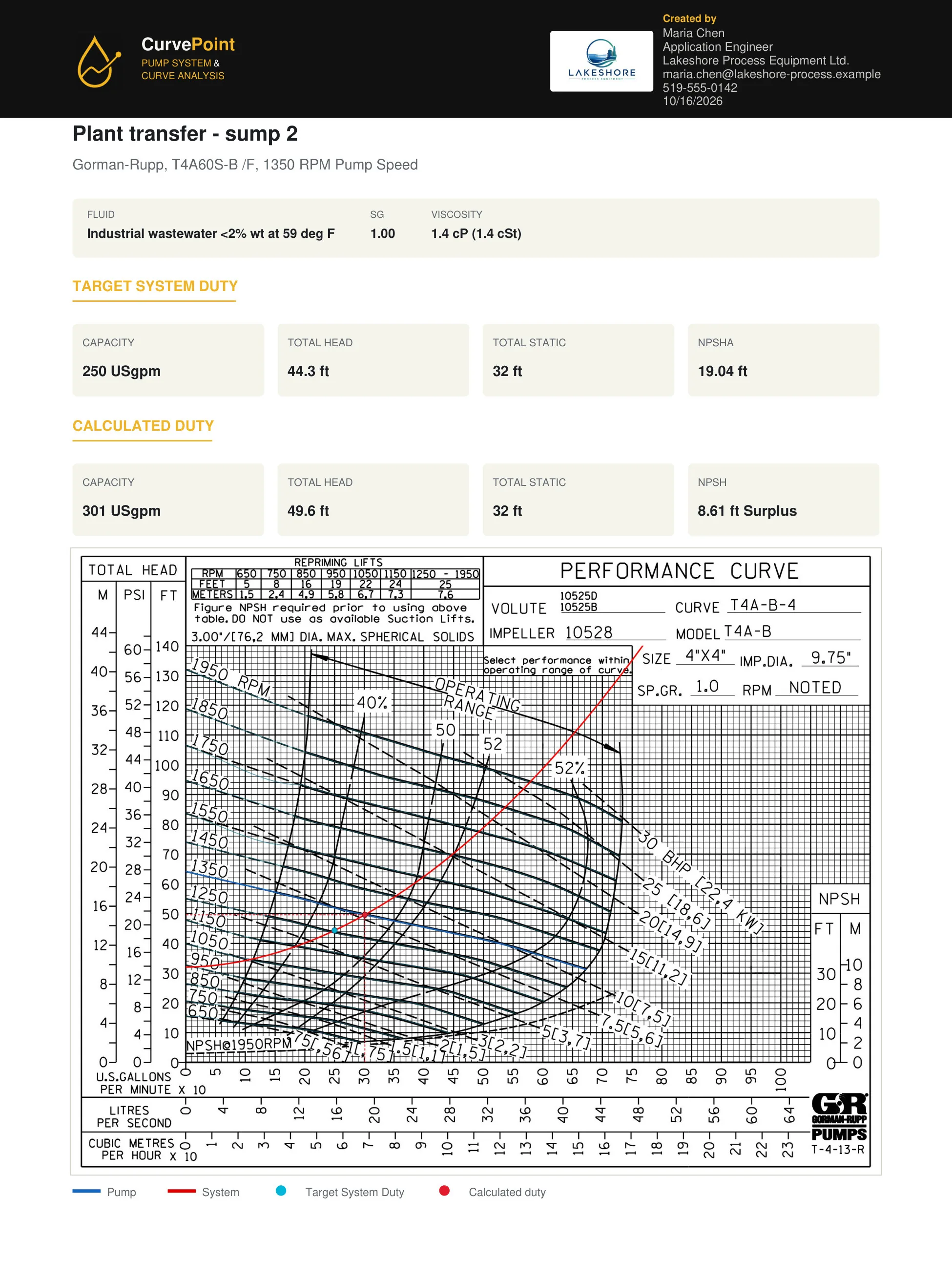
The station the report describes
The pump is a self-priming centrifugal set above the liquid. Static suction lift is 12 ft from the free surface up to the pump centerline. Static discharge head is 20 ft above that same centerline. Total static head is 32 ft, and it does not change with flow. The suction line is 4 in Schedule 40 commercial steel, 15 ft long, with a sharp-edged inlet and one standard 90° elbow. The discharge is the same pipe, 250 ft long, with four long-radius 90° elbows, a full-open gate valve, a swing check, and an outlet into the receiving tank. Those are the fittings the recompute uses. If your station has a strainer or a second valve, it is a different system curve.
The fluid is industrial wastewater under 2 percent solids by weight, at 59°F. The sample treats it as hydraulically close to water. Viscosity in the recompute is 1.36 cP, matching the report, and vapour pressure is 0.25 psia. Site altitude is 1,000 ft, so atmospheric pressure is not sea-level air. The catalog specific gravity used here is 1.003. The PDF rounds specific gravity to 1.00 and lists density near 1,001 kg/m³. That rounding is smaller than the other uncertainties in a lift station, and the page still marks the head as an estimate.
Head at 301 gpm
The sample’s calculated duty is the intersection of this system curve with the published curve at 1,350 RPM: 301 gpm and 49.6 ft. The table recomputes the piping at that same 301 gpm without redrawing the pump curve, which is why it can confirm the system head but cannot, by itself, rediscover the intersection. You will see total head a little under 49.6 ft, printed on the PDF as 49.57 ft in the head breakdown and rounded to 49.6 ft on the duty line. Static head is 32 ft. Suction friction is about 1.50 ft. Discharge friction is about 16.07 ft. Total dynamic suction lift is lift plus suction friction, about 13.5 ft. Total dynamic discharge head is 20 ft plus discharge friction, about 36.07 ft. Add those two dynamic heads and you are back at total head. Nothing in that split is a manufacturer’s guarantee. It is Darcy-Weisbach plus the fitting losses, evaluated by the app.
The report also prints a target, separate from the intersection: 250 gpm, 44.3 ft of total head, 32 ft static, and NPSH available of 19.04 ft. The target is the flow someone hoped to hit. The intersection is the flow the curves actually share. They are not the same number, and the report shows both so a reviewer can see the pump is to the right of the target on this line. If the target were mandatory, the next conversation would be a speed change or a different curve, not a quieter font on the PDF. That conversation is the subject of the pump curve versus system curve page.
NPSH on the same duty
At 301 gpm the suction side has spent 12 ft of lift and about 1.5 ft of friction. Atmospheric head at the sample altitude is about 32.65 ft of this liquid. Vapour-pressure head is a little over half a foot. What remains is NPSH available. The recompute lands near 18.57 ft. The PDF prints 18.58 ft. Use the PDF figure when you cite the sample, and treat both as estimates from the same method.
The curve reading entered for the study is 8 ft. In the app that field is NPSHr, the water-curve value, not a calculated suction head. CurvePoint’s general industrial margin check, applied to that 8 ft reading, estimates a required value of 9.97 ft. Surplus is available head minus required head, about 8.6 ft, and the PDF marks it as a pass. A pass on a fictional dilute wastewater at 59°F is not a pass for a hotter, gassier, or thicker liquid, and it is not a pass at a higher flow where both friction and the curve reading get worse. The NPSH calculator lets you move atmosphere, lift, friction, and vapour pressure one at a time. The suction lift guide explains why this 12 ft lift is a reasonable teaching case and not a number to copy onto every wet well.
One pump in a station that has two
The table above is a separate illustration, Lakeshore Station 3, calculated as one pump. The suction is 6 in by 12 ft. The discharge branch is 4 in by 15 ft, with long-radius elbows, a swing check, a plug valve, and the branch of a tee. A 6 in header and a 6 in force main, 2,400 ft, follow in series. Static head is 20 ft on the discharge, plus 8 ft of lift at low water, 4 ft at high water, or a flooded suction that adds nothing on the suction side. New commercial steel uses the catalog roughness. The aged rows raise ε to ten times that catalog value, labeled as an illustration of an older main.
Read the velocity column against the 3–6 ft/s band Reno’s lift-station standard uses for review with one pump running. On new steel the duty is outside that band. The aged main moves the intersection left and the velocity falls inside it. The best-efficiency share uses CurvePoint’s estimate of best efficiency, the flow where flow times head is greatest, because this illustration has no efficiency test. Those shares sit inside the 50–120 percent window Houston asks reviewers to look at. Both bands are city standards. Confirm the edition you design to.
A real duplex station repeats the branch: a check valve and a plug valve on each pump, then the shared header and the force main. With two pumps running, each branch still sees its own flow and the force main sees the sum, so the second pump does not double the one-pump duty. CurvePoint’s result on this page is the individual pump. It does not solve the combined curve. Moore County’s force-main standard is one public reminder to check every operating condition, including a main that more than one station shares. Seattle’s pump-station chapter asks for individual and combined curves. The combined case stays prose until the solver grows a branch-and-shared model.
The swing-check table is the same 4 in branch at two flows. Loss grows with velocity squared, which is why a check that looks small at 200 gpm is a different number at the low-well duty. A 2-vane open solids-handling impeller, common where rags have to pass, is a poor candidate for scaling this curve to another speed. The affinity-law guide shows where that estimate drifts, especially when static head dominates.
Who runs the station, and what a bypass has to show
In Ontario, O. Reg. 129/04 and the provincial licensing guide class wastewater collection and treatment facilities from Class I through Class IV. The Ontario Water Wastewater Certification Office administers that licensing for the ministry. The guide ties those licences to municipal or Crown sewage works that need an Environmental Compliance Approval. An industrial-only sewage works generally sits outside that operator licence unless the approval says otherwise, or unless domestic sewage is combined with the industrial flow. The provincial permissions page is where that approval is described.
Ragging is a separate problem from the hydraulic duty. EPA’s preliminary-treatment material treats rags, wipes, and grit as something the pump and the upstream screens have to pass or remove. A speed change does not clear a plugged impeller.
Bypass pumping during a repair is related work, and it is not a second calculator on this page. Published specifications, including San Marcos and Minot, expect a plan that covers peak flow, the suction and discharge points, total dynamic head, and pump curves. Some of those specifications require a licensed engineer to prepare the plan. Minot asks for a bypass contractor with five comparable projects in the last ten years. Seattle’s bypass specification asks for automatic self-priming pumps that pass 3 in solids and rags, run dry on continuous duty, use no foot valves or vacuum pumps, and bring 100 percent redundant capacity plus standby power and round-the-clock monitoring logged every five minutes. Plugs in that specification are rated for the seating head plus 5 ft. Minot and American Water call for fused or restrained HDPE on the temporary line, and those specifications prohibit glued PVC and aluminium irrigation pipe. Secondary containment and a spill plan sit beside the pumps in those same specifications. Bring the one-pump curve from this page into that plan, and calculate the second pump as its own study until a combined model exists.
| Published threshold | Average flow |
|---|---|
| 25,000 US gal/day of process wastewater | 17.36 gpm (1.10 L/s) |
Illustrative Lakeshore Process Equipment figures from CurvePoint’s own evaluation. Not a sealed calculation.
A US industrial user that discharges process wastewater to a municipal plant can fall under the national pretreatment rules in 40 CFR Part 403. EPA’s applicability material treats 25,000 gallons per day of process wastewater, among other tests, as one way a user becomes significant. The table converts that daily volume with CurvePoint’s gallon factor so it can be compared with a pump duty. Those users monitor, report, and keep records. A slug control plan can be required when a batch could upset the municipal plant. Hot industrial wastewater spends NPSH on vapour pressure the same way the NPSH calculator shows for warm water. The 301 gpm sample above stays the dilute, cool case printed on the PDF.
How to read the PDF and the video
Page one of the PDF is the picture above: identity block, fluid, target duty, calculated duty, and the curve with the intersection marked. Later pages carry the segment table, the head tape, the NPSH ledger, the method notes, and a schematic with the 12 ft lift and the 20 ft discharge head drawn from the pump centerline. The schematic warns that elevations are approximately to scale and that pipe lengths and fittings are not. Do not scale the 250 ft force main off the sketch. Read the segment table.
The video is the same product, narrated, walking a study rather than this article. Watch it if you want to see axes, plotting, and the moment the operating point appears. Then open the calculator and either start clean or edit the water and wastewater suction-lift preset until the lengths match this example: 15 ft of suction, 250 ft of discharge, 12 ft of lift, 20 ft of discharge head, 4 in steel. Plot a curve at the speed you will run. The free study shows the intersection and the NPSH check on screen. Pro, described on pricing, is what puts that study into the PDF format you just opened.
Lakeshore Process Equipment, the phone number, and the email on the PDF are placeholders. Do not call them and do not treat the 1,350 RPM curve as a recommendation of any manufacturer. CurvePoint is an independent tool. Use the sample to learn the sheet, then replace every input with the station you are actually quoting. The system curve calculator is the short version of the piping math, and the homepage is where this example sits next to the product.